Motorcycle Traction-Control Research Platform
Several years ago I wanted to experiment with a question that is easy to describe and much harder to test properly: can useful motorcycle traction-control behaviour be explored by intervening only in fuel injection?
The idea was not to replace the motorcycle ECU. Instead, I wanted a research platform that could sit between the motorcycle and several of its existing signals, observe what was happening in real time, and — when explicitly commanded — alter injector operation. In normal operation it had to behave as transparently as possible.
The resulting prototype interfaced with the injector channels, wheel-speed/ABS signals and throttle-position signal. Its purpose was not to be a finished road-going traction-control product. It was an instrumented platform on top of which different fuel-cut strategies could be measured, logged and tested.
Conceptually, the setup looked like this — two microcontrollers, with the safety-critical signal paths deliberately quarantined from everything else:
                          ┌──────────────────────────────────────┐
  front / rear wheel  ───>│  CRITICAL MCU (PIC18F25K42)          │───> ABS ECU
  engine ECU injector ───>│  wheel-speed + injector pass-through │───> injectors
                          └───────────────────┬──────────────────┘
                                              │ intervention requests
                          ┌───────────────────┴──────────────────┐
  throttle position   ───>│  LOGIC MCU (PIC18F25K42)             │───> engine ECU
                          │  acquisition · logging · telemetry   │
                          │  experimental control logic          │
                          └──────────────────────────────────────┘
The simple block diagram hides most of the difficult work. Injector outputs are inductive power loads, wheel-speed sensors are not necessarily convenient logic-level devices, the TPS is an analog signal the ECU expects to remain trustworthy, and a motorcycle electrical system is a noisy environment. A useful interceptor therefore has to understand the signals electrically before it can attempt to understand them algorithmically.
Measure first, design second
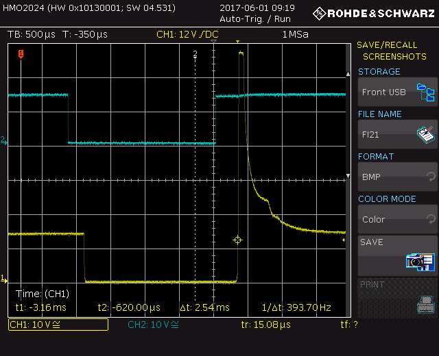
The project started with measurements on a 2010 Honda CBF600. A Rohde & Schwarz digital oscilloscope was used to capture injector voltage and current, throttle position and wheel-speed signals under different conditions.
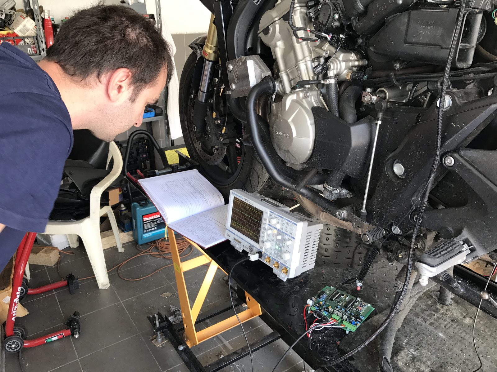
I also installed a Dynojet Power Commander V and measured the same injector channels with and without it. This was particularly useful: the PCV is itself an inline device that modifies injector behaviour, so it provided a real commercial reference for what an ECU interceptor looks like electrically.
One of the first useful observations was simply the injector current ramp. The injectors on the test bike behaved as conventional saturated injectors, with current rising to roughly the ampere range during an injection event.
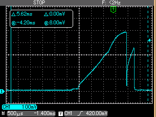
Injection itself is only a millisecond-scale event, so preserving its timing matters. At idle the measured pulse width was on the order of a few milliseconds and it changed with operating conditions. The platform therefore needed timing resolution comfortably below the scale of the injection pulse itself.
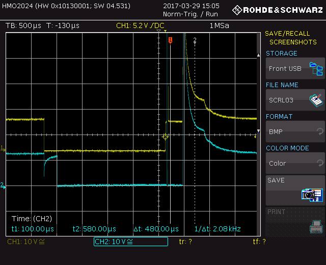
The PCV measurements were also interesting because its output was not an electrically perfect copy of the Honda ECU signal. The timing relationship was close, as expected, but the switching transitions and inductive flyback behaviour differed noticeably.
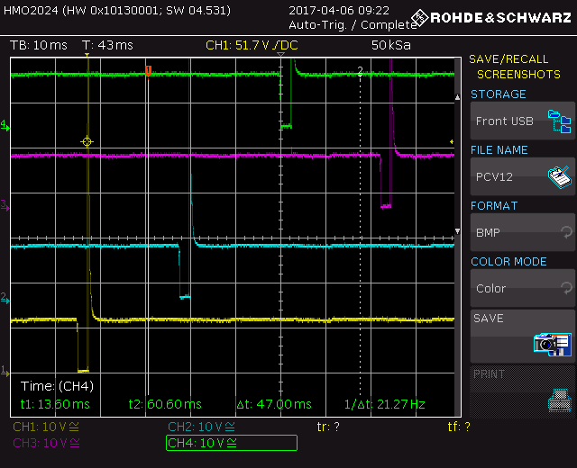
Looking at multiple channels also confirmed the event sequence and, more importantly for the project, the amount of time available to observe one event, make a decision and prepare for the next one.
The inconvenient part: injectors are inductive loads
An injector is a solenoid. Switching it off does not make its current disappear instantly; the stored magnetic energy has to go somewhere. The result is an inductive voltage transient that can be many times higher than the motorcycle battery voltage.
That detail is important for two reasons. First, the output stage needs to survive it repeatedly. Second, the way the transient is handled affects how quickly the injector closes. A protection circuit that is electrically safe but changes the injector’s closing behaviour too much is not necessarily transparent from the engine’s point of view.
The stock Honda ECU and the PCV handled this transient differently in my measurements. The PCV produced a substantially higher flyback peak, while the original ECU limited it more aggressively.
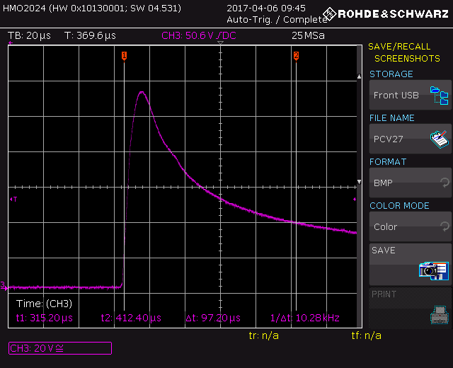
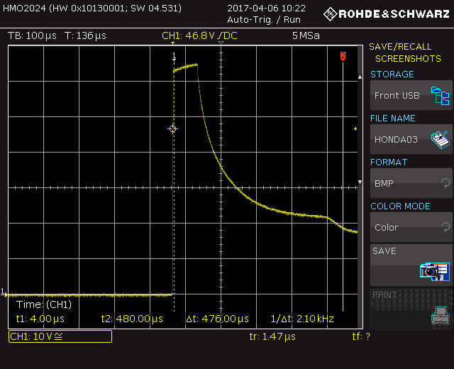
This comparison influenced the design far more than a schematic based only on nominal injector resistance would have done.
Wheel speed is not just another digital input
A traction-control experiment needs some estimate of wheel slip, which makes front and rear wheel speed the obvious starting point. The existing ABS sensors are attractive because the motorcycle already has robust wheel sensing hardware in exactly the right places.
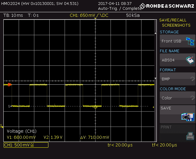
But the measured signal was not a convenient 0/5 V logic waveform. It was a relatively small, biased signal whose state had to be detected reliably without disturbing the ABS ECU. That meant the wheel-speed interface had two jobs: preserve the original sensor/ECU relationship and produce a clean internal representation suitable for precise timing measurements.
The throttle-position channel created a different problem. On this motorcycle it is essentially an analog position signal spanning the familiar sub-1 V to roughly 4.5 V range. For traction-control research that signal is useful context — the same wheel-speed difference means something different with the throttle closed than it does under hard acceleration — but inserting electronics into an ECU sensor path demands very low error and predictable behaviour.
Splitting real-time control from data acquisition
One architectural decision proved especially useful: the time-critical injector path was kept separate from the slower measurement and communication work.
This was enforced in hardware rather than by discipline alone. The prototype used two PIC18F25K42 microcontrollers with a deliberate division of responsibility. One was dedicated entirely to the safety-critical paths — the injector channels and the ABS wheel-speed signals — and did nothing else. The second handled everything that was merely important: throttle acquisition, logging, telemetry, the experimental control logic and all external communication.
The distinction matters more than it might sound. The critical MCU has one obligation it can never miss: an injector command arrives and must be forwarded with correct timing, every time, regardless of what the rest of the system happens to be doing. Sharing that processor with a logging routine, a wireless stack or an unfinished control experiment would mean that any bug anywhere in the non-critical code could turn into a missed or mistimed injection event on a running engine. Keeping those two worlds on separate silicon meant the second MCU could be freely re-flashed and experimented with while the injector and ABS paths kept behaving identically.
The second processor could request an intervention, but it could not disturb the timing of the path that carried it out.
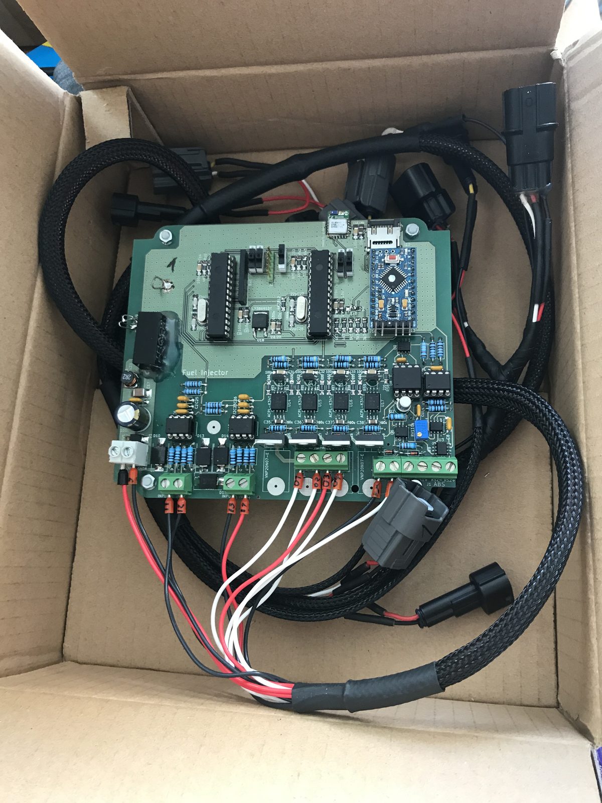
The prototype also had local data logging and a wireless control/telemetry path. During development this made it possible to collect signals on the motorcycle without turning every test into a laptop-and-oscilloscope exercise.
I am intentionally leaving the detailed implementation out of this article. The original project archive contains the complete PCB work, protection and conditioning circuits, component selection, test fixtures and the lower-level timing details. Those were a significant part of the engineering effort, and the useful public story does not require publishing a build recipe.
Transparent operation was the first milestone
Before experimenting with traction control, the system had to prove that doing nothing was safe and boring.
That meant running the injector path through the prototype while commanding no modification, then comparing input and output waveforms. Similar validation was done for the sensor interfaces. The goal was not merely that the engine continued to run; it was that the important timing and electrical characteristics remained close enough to the original system that the motorcycle could not meaningfully tell that another device had been inserted into the path.
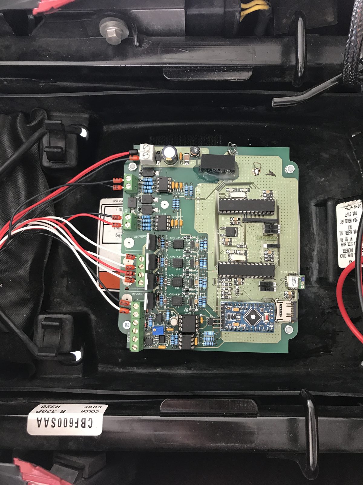
The development process moved in stages: characterize the motorcycle, reproduce signals on the bench, validate individual input and output stages, assemble the full PCB, test transparent forwarding, and only then treat the hardware as a platform for control experiments.
That sequence is probably the most reusable lesson from the project. With automotive electronics it is very tempting to start from the algorithm — calculate slip, choose a threshold, cut some fuel — but the algorithm is almost the easy part. The difficult foundation is knowing that every measurement is real, every output behaves as expected, and the system remains predictable when nothing interesting is supposed to happen.
What the platform was intended to enable
Once the interceptor existed, experiments could be expressed at a much higher level. The system could observe front and rear wheel timing, throttle position, engine/injection timing and then decide whether selected future injection events should be passed through or suppressed.
That makes several research questions testable without replacing the stock ECU:
- how quickly a useful wheel-speed difference can be detected;
- how much filtering is needed before that difference becomes trustworthy;
- whether fuel-cut patterns can reduce torque smoothly enough to be useful;
- whether intervention should depend on throttle position and engine speed;
- how aggressively fuel can be restored after the wheel-speed difference collapses;
- and how all of those decisions affect the motorcycle when measured rather than simulated.
The important distinction is that this was a traction-control research platform, not a claim of a finished traction-control system. Its purpose was to make those questions measurable and repeatable.
Looking back
The project was built in 2017, and the archive is a nice snapshot of how much engineering can sit behind something that sounds simple in one sentence: “put a microcontroller between the ECU and the injectors.”
The most valuable part was not any individual circuit. It was the measurement-first approach. The OEM ECU, the PCV, the injectors, ABS sensors and TPS were all treated as systems to be observed before they were treated as interfaces to be controlled.
That left me with a hardware platform capable of transparently monitoring the motorcycle and selectively taking control of fuel injection — exactly the foundation I wanted for further traction-control experiments based on fuel cut.
Note: this was an experimental engineering platform for controlled research. Injector and ABS interfaces are safety-critical vehicle systems; the article intentionally omits the information needed to reproduce the hardware.